How to Wire a Light Switch (Single-Pole & 3-Way)
Recent buzz, like the 'DIY electrical project for wiring a light switch💡' mention via MSN, highlights a common homeowner undertaking. While replacing or installing a light switch can seem straightforward, it involves working with electricity, which always requires caution and adherence to safety standards. Understanding the basics of electrical wiring, proper wire selection, and the specific configurations of different switch types is crucial for a safe and successful project.
This guide provides step-by-step instructions for wiring common household light switches – single-pole and 3-way – emphasizing safety precautions and the importance of using the correct wire gauge. Always remember that if you're uncomfortable at any point, it's best to consult a qualified electrician.
Safety First: Essential Precautions for Electrical Work
Working with electricity carries inherent risks. Prioritizing safety is paramount to prevent injury or damage. Before beginning any electrical work:
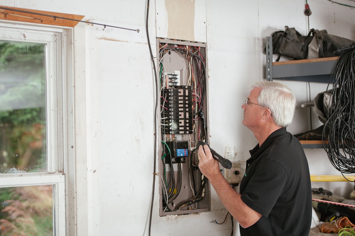
- Turn Off Power: Locate the circuit breaker that controls the light switch you're working on and flip it to the 'OFF' position. For critical projects, consider turning off the main breaker to the entire house.
- Verify Power is Off: Use a non-contact voltage tester to confirm that no power is present at the switch box. Touch the tester to the wires you intend to work with. If it indicates power, double-check the breaker.
- Wear Protective Gear: Always wear insulated gloves and safety glasses.
- Use Insulated Tools: Ensure your screwdrivers, pliers, and wire strippers have insulated handles.
- Inspect Wiring: Check existing wiring for any signs of damage, fraying, or burning. If found, consult a professional.
- Consult Local Codes: Electrical codes can vary by jurisdiction. Always check your local electrical codes and obtain any necessary permits before starting work (Understanding NEC Code Editions can be a useful resource).
- When in Doubt, Call a Pro: If you are unsure about any step or encounter unexpected wiring, stop and contact a licensed electrician.
Understanding Common Light Switch Types
Most residential lighting circuits use one of two main types of switches:
- Single-Pole Switch: This is the most common type, used to control a light fixture from a single location. It has two terminal screws (often brass or silver) for the 'hot' wires and one green or bare copper screw for the ground wire.
- 3-Way Switch: Used when you need to control a single light fixture from two different locations (e.g., at the top and bottom of a staircase, or both ends of a hallway). A 3-way switch has three terminal screws (one 'common' screw, usually darker or marked, and two 'traveler' screws) plus a green or bare copper ground screw. You will always need two 3-way switches to complete a 3-way circuit.
How to Wire a Single-Pole Light Switch
This guide assumes you are replacing an existing switch or installing new wiring in a standard setup where power enters the switch box first.
- Prepare the Work Area: Ensure power is off and verified. Remove the existing switch plate and switch from the electrical box. Carefully pull the wires forward.
- Identify Wires: You should see a bare copper or green wire (ground) plus the two hot conductors — one bringing power from the circuit breaker (the 'line' or 'hot incoming') and one going to the light fixture (the 'load' or 'hot outgoing'). When power runs to the box first, both of these are usually black. But in a switch-loop wiring scheme (where power reaches the light fixture first), you will instead see a black wire and a white wire at the switch. In that case the white is not a neutral — it is a re-identified switched hot and, per NEC 200.7(C)(2), it should be marked with black or red tape or marker at both ends. Treat that white conductor as hot, never as a neutral.
- Connect the Ground Wire: Connect the bare copper or green ground wire from the electrical box to the green or bare copper ground screw on the new switch. If there are multiple ground wires, use a pigtail connection to connect them all to the switch. (Grounding and Bonding Basics provides more detail.)
- Connect the Hot Wires: Connect the incoming hot wire (power from the breaker) to one of the brass or silver terminal screws on the switch. Connect the outgoing hot wire (power to the light fixture) to the other brass or silver terminal screw. It typically doesn't matter which hot wire goes to which brass terminal on a single-pole switch.
- Secure and Test: Carefully fold the wires back into the electrical box. Mount the switch securely into the box, attach the switch plate, and restore power at the circuit breaker. Test the switch to ensure the light turns on and off correctly.
How to Wire a 3-Way Light Switch
Wiring 3-way switches is more complex due to the traveler wires. You'll have two switch boxes involved.
- Prepare and Identify: Ensure power is off and verified at both switch locations. Remove existing switches. You'll typically find three hot wires (two travelers and one common) plus a ground wire in each box. Identify the 'common' wire (the hot wire bringing power *to* the first switch or sending power *from* the second switch to the fixture) – this is usually connected to a darker-colored screw.
- Ground Wires: Connect all bare copper or green ground wires in each box to the green or bare copper ground screw on each respective 3-way switch.
- Connect Common Wires:
- At the First 3-Way Switch (where power enters): Connect the incoming hot wire (from the circuit breaker) to the common terminal screw of the first 3-way switch.
- At the Second 3-Way Switch (where power leaves to the fixture): Connect the hot wire that runs to the light fixture to the common terminal screw of the second 3-way switch.
- Connect Traveler Wires: The remaining two hot wires in each box are your traveler wires. Connect these two traveler wires to the two traveler terminal screws (typically lighter colored) on the first 3-way switch. Then, connect the *same two* traveler wires (they run between the two boxes) to the two traveler terminal screws on the second 3-way switch. It's crucial that each traveler wire connects to a traveler screw on *both* switches.
- Secure and Test: Carefully fold wires into both electrical boxes. Mount both switches, attach switch plates, and restore power. Test both switches to ensure the light can be controlled from both locations.
Choosing the Right Wire Gauge
The wire gauge you use for your light switch circuit is critical for safety and performance. Using wire that is too small for the circuit's amperage can lead to overheating, fire hazards, and excessive voltage drop, especially over longer distances. The National Electrical Code (NEC) provides guidelines for wire ampacity based on gauge.
Most standard residential lighting circuits are on 15-amp or 20-amp breakers. For 15-amp circuits, 14-gauge wire is typically used, while 12-gauge wire is common for 20-amp circuits. However, factors like conductor material (Copper vs Aluminum Wire), insulation type, and ambient temperature can affect ampacity.
To ensure you're using the correct wire size for your specific installation, especially considering voltage drop over longer runs, use our free wire size calculator. It helps you determine the appropriate gauge based on the circuit's amperage and length, ensuring your wiring complies with safety standards and performs optimally. For more detailed information, explore our guide on How to Size Electrical Wire.
Copper THHN ampacity at 75°C by AWG (NEC 310.16)
Key Takeaways
- Always turn off power at the circuit breaker and verify with a voltage tester before starting any electrical work.
- Single-pole switches control a light from one location, connecting incoming and outgoing hot wires to two terminals.
- 3-way switches control a light from two locations, requiring two switches and using common and traveler wires.
- Proper wire gauge is essential for safety and efficiency; use a wire size calculator to match wire to circuit amperage and length.
- If uncertain or uncomfortable, always consult a licensed electrician to ensure safety and compliance with local codes.
Try It Yourself — Free
Ensuring your electrical wiring is correctly sized is vital for safety and performance. Utilize our free wire size calculator to quickly determine the appropriate wire gauge for your projects. You might also find our Breaker and Load Calculation Basics guide helpful for understanding your home's electrical capacity.
Related Resources
- Breaker and Load Calculation Basics
- Copper vs Aluminum Wire
- Ev Charger Wire Size Calculator
- Ev Charger Wire Size Guide
- Complete Guide
More From Our Network
- Duct Size Calculator — same niche
- cyberfrad — our network
Sources
- MSN — Original report
- MSN — DIY electrical project for wiring a light switch💡 - MSN
- National Fire Protection Association (NFPA) — Wire gauge selection is based on ampacity requirements, as detailed in the National Electrical Code (NEC), to prevent overheating and ensure safe operation.